

To follow this series comfortably, you need a firm grounding on the workings of Cortex-M processors, including but not limited to its instruction set architecture(ISA), memory system organization, exceptions and interrupts and its salient features.
I dedicate this article to a brief discussion of the key architectural features of ARM Cortex-M3/M4 processors. Detailed knowledge of the processor is not required at first, as we will be doing most programming in a high-level language with standard libraries, which abstracts away most of these details. But as you advance in your design, you may need to implement critical functions in assembly language to improve efficiency. This requires a comprehensive understanding of this processor, so it is worth learning its intricate features.
Cortex-M family
Cortex-M microcontrollers are based on the ARM Cortex-M processor core, a 32-bit RISC (Reduced Instruction Set Computing) architecture optimized for low-power, high-speed operation. Cortex-M microcontrollers are available in various performance and feature configurations and are typically used in applications that require low power consumption, real-time performance, and deterministic behaviour.
The Cortex-M3 and Cortex-M4 are both 32-bit microcontroller architectures developed by ARM Holdings. They are members of the Cortex-M family of microcontrollers designed for use in embedded systems.
The Cortex-M3 is a low-power, high-performance microcontroller architecture optimized for cost-sensitive, real-time applications. It includes various features and peripherals suitable for embedded applications, including consumer electronics, industrial control, and automotive systems.
The Cortex-M4 is an enhanced version of the Cortex-M3, with additional features and capabilities that make it suitable for more demanding applications. It includes a floating-point unit (FPU), which allows it to perform single-precision floating-point arithmetic. It also has additional instructions and memory protection features, making it more suitable for safety-critical systems.
Both the Cortex-M3 and Cortex-M4 are supported by a wide range of development tools and software, including compilers, debuggers, and real-time operating systems (RTOS). They are commonly combined with various external devices and peripherals, such as sensors, displays, and communication interfaces, to create complex embedded systems.
ARM Holdings is a British multinational semiconductor and software design company. ARM does not manufacture processors but instead licenses its designs to other companies, producing their processors based on ARM's architectures. ARM's business model is based on licensing its processor designs and IP to other companies, which pay royalties for using ARM's technology. This allows ARM to focus on the development and evolution of its processor architectures while leaving the manufacturing and production of processors to its licensees. Some major companies that manufacture processors and microcontrollers based on ARM's architectures include Qualcomm, Samsung, Apple, Huawei, Mediatek, NXP, STMicroelectronics, Atmel, Microchip, and Texas Instruments.
General considerations
Operation states
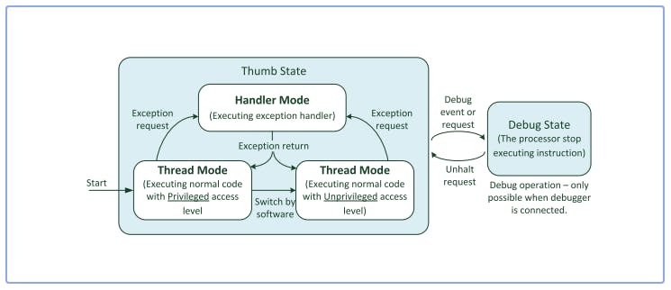
Thumb state: This is the default operational state of the Cortex-M processor, which executes instructions from the Thumb instruction set. The Thumb instruction set is a reduced instruction set designed to provide good code density and efficient execution.
Debug state: The Cortex-M processor can enter the debug state when it is being debugged using a debugger or emulator. In this state, the processor can be stopped, single-stepped, or run under the debugger's control.
Operation modes
Thread mode: This is the default operational mode of the Cortex-M processor, in which the processor executes instructions from a single task or thread. In thread mode, the processor can access its resources, including its registers, memory, and peripherals.
Handler mode: The Cortex-M processor can enter handler mode when executing an interrupt or exception handler. In handler mode, the processor can access a reduced set of resources, including its registers and memory, but not its peripherals.
Register organiszation
The Cortex-M3 and Cortex-M4 processors have several internal registers to perform data processing and control. These registers are grouped in a unit called the register bank. The Cortex-M3 and Cortex-M4 processors use a load-store architecture in which data in memory must be loaded into registers in the register bank to be processed and then written back to memory if needed. This arrangement allows efficient program code to be generated using C compilers, as data variables can be stored in the register bank for a short period while other data processing takes place. The register bank in the Cortex-M3 and Cortex-M4 processors has 16 registers. Thirteen of them are general-purpose 32-bit registers, and the other three have special uses.
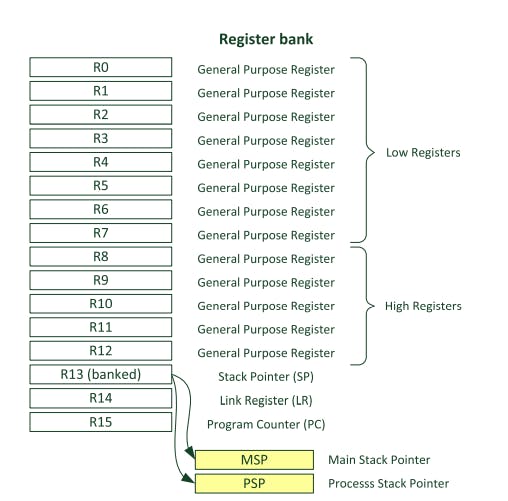
The Cortex-M processor has a set of general-purpose registers numbered R0 to R12, with the first eight (R0 to R7) referred to as low registers and the remaining registers (R8 to R12) referred to as high registers. Most 16-bit instructions can only access the low registers, while the high registers can be used with both 32-bit and a few 16-bit instructions. The initial values of these registers are not defined.
The Stack Pointer (R13) is used for accessing the stack memory via PUSH and POP operations. There are two Stack Pointers: the Main Stack Pointer (default Stack Pointer) and the Process Stack Pointer.
The Link Register (R14) is a 32-bit register part of the Cortex-M processor's register bank. It is often used with the Stack Pointer (SP) register to store and retrieve the return address when calling and returning from functions.
The Program Counter (PC) is a special-purpose register that stores the address of the instruction that the processor is currently executing.
Besides the registers shown in the register bank above, there are some special registers the processor uses for various purposes, such as controlling the processor's operation, storing exception information, and maintaining the processor's state. These registers are rarely used in most cases.
Memory system and peripherals
The memory map of the Cortex-M processor is the layout of the processor's memory space, which determines how different regions of memory are accessed and used by the processor. The Cortex-M processor has a 32-bit memory space, which means it can address up to 4 gigabytes of memory.
The Cortex-M processor's memory map is divided into several regions, each with a specific purpose. Some of the main areas of the Cortex-M processor's memory map include the following:
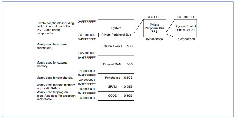
Code memory: This is the region of memory that stores the instructions executed by the processor. The code memory is usually located at the beginning of the memory map and is typically read-only, meaning that the processor cannot modify it.
Data memory: This is the region of memory that stores the data used by the processor. The data memory is typically located after the code memory and is divided into several areas, including the stack, heap, and static data.
Peripheral memory: This is the region of memory that is used to access the processor's peripherals, such as timers, serial ports, and analogue-to-digital converters. The peripheral memory is typically located at the end of the memory map and is accessed using memory-mapped I/O.
System memory is the region of memory used by the processor's operating system or other system-level software. The system memory is typically located after the data memory and stores system control registers and other system-level data.
Bus system
In a Cortex-M microcontroller, the bus system refers to the system of interconnected hardware components that communicate with each other and with the central processing unit (CPU). The bus matrix is a component of the bus system that serves as a central hub, routing data and instructions between the various peripherals and the CPU.
The Cortex-M microcontroller has a Harvard architecture, which means it has separate memories for instructions and data. The bus system transfers data and instructions between these memories and the peripherals. The bus matrix is the component that routes these transactions to their intended destinations.
AHB (Advanced High-performance Bus) and APB (Advanced Peripheral Bus) are two buses commonly used in Cortex-M microcontrollers.
AHB is a high-speed bus that connects the CPU and other high-speed peripherals, such as the memory controller, DMA controller, and external interfaces. AHB is designed to be fast and efficient, with a high-bandwidth and low-latency design.
On the other hand, APB is a slower bus that connects slower peripherals, such as UARTs, timers, and ADC/DACs. APB is designed to be simple and low-power, with a low-bandwidth and low-complexity design.
Exceptions and interrupts
Exceptions and interrupts are types of events that can cause the CPU to halt its current activity and execute a specific routine temporarily.
Exceptions are events that are internally generated by the CPU, such as divide-by-zero errors or illegal instruction fetching. When an exception occurs, the CPU stops its current activity and transfers control to a specific exception handler routine. The exception handler routine can then take appropriate action, such as logging the error or resetting the system.
Interrupts, on the other hand, are events externally generated by peripherals or other hardware components. When an interrupt occurs, the CPU stops its current activity and transfers control to a specific interrupt handler routine. The interrupt handler routine can then take appropriate action, such as servicing the request or completing a task.
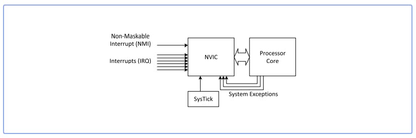
NVIC (Nested Vectored Interrupt Controller) is a component of the Cortex-M microcontroller that manages interrupts. It is responsible for determining the priority of interrupt requests and routing them to the appropriate interrupt handler routine.
The NVIC has some interrupt request lines connected to a specific peripheral or another hardware component. When an interrupt request is received, the NVIC determines the priority of the request and routes it to the appropriate interrupt handler routine. The NVIC also maintains a list of pending interrupts and ensures that they are serviced in the correct order.
The NVIC allows the Cortex-M microcontroller to efficiently manage interrupt requests and ensure that they are handled promptly and appropriately. This is important for real-time systems and other applications where quick response to events is critical.
References
Yiu, J. (n.d.). The definitive guide to ARM Cortex-M3 and Cortex-M4 processors, third edition. Newnes Uuuu-Uuuu.
Tahir, M. and Javed, K. (2017). ARM Microprocessor Systems. CRC Press.