

General Purpose Input/Output are typically pins found on a computer or microcontroller board that can interface with external devices. Software can configure these pins as inputs or outputs at runtime, allowing them to send or receive electrical signals to control or monitor external devices such as LEDs, sensors, or motors. GPIO gives high flexibility of use and convenience to embedded system design, as the number of pins on processors is limited, and they can be configured on the fly to serve a given function.
GPIO pins are grouped on a computer or microcontroller board and are typically organized into ports (usually a group of 8 pins). Software can configure GPIO pins to perform any of the following functions:
Digital I/O function.
Analog I/O functions.
Advanced functions including PWM, LCD drivers, USART, SPI, PC and USB communication.
Input Modes: Pull-Up and Pull-Down
When a GPIO pin is configured as a digital input pin, there are three possible states the pin can exist in: HIGH, LOW or Hi-Z(high impedance or tristate). Pull-up and pull-down resistors are used to provide a known state for an input pin when it is not connected to anything or when it is not being actively driven. This prevents the input pin from floating and reliably represents a valid digital state.
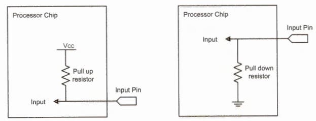
A "pull-up" resistor is a resistor that is connected between the input pin and VCC. This resistor "pulls" the input pin to VCC, the supply voltage when an external device is not driving the pin. This ensures a stable high level when the pin is not being used or driven by an external device. Similarly, a "pull-down" resistor connects the input pin and GND. This resistor "pulls" the input pin to a low voltage level, typically 0V when an external device is not driving the pin. This ensures a stable low level when the pin is not being used or when an external device is not connected.
Output Modes: Push-Pull and Open-Drain
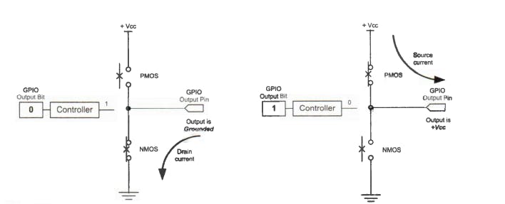
A "push-pull" output configuration(shown above) uses two transistors, one NPN and one PNP, to drive the output pin. When the NPN transistor is turned on, it "pushes" the output pin to the supply voltage, VCC. When the PNP transistor is turned on, it "pulls" the output pin to GND, usually 0V. This allows the output pin to be driven to high and low voltage levels, making it a bidirectional output.
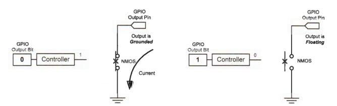
On the other hand, an "open-drain"(shown above) output configuration uses only a single NMOS transistor to drive the output pin. When the transistor is turned on, it "drains" the current from the output pin, pulling it to a low voltage level. When the transistor is turned off, the output pin is "open" and is in a high-impedance state, meaning it is effectively disconnected from the circuit.
Memory VS Port-Mapped I/O
Memory-mapped and port-mapped I/O are two different approaches to accessing and controlling IO devices connected to the GPIO of MCUs.
In "memory-mapped I/O," the I/O devices are connected to the MCUs memory bus and are accessed using memory addresses. This means that the I/O devices are mapped to the address space of the MCU and are treated as if they were part of the MCU and can be read from and written to using the same instructions used to access memory. This approach allows for easy integration of I/O devices into the MCU architecture and eliminates the need for special I/O instructions.
On the other hand, "port-mapped I/O" uses separate addresses for input and output operations; the I/O devices are connected to the MCU through a separate I/O bus and are accessed using special I/O instructions. This approach allows for more direct control over the I/O devices and can be faster than memory-mapped I/O at the expense of the overall MCU architecture complexity.
In ARM Cortex-M processors, memory-mapped I/O is used for accessing and controlling peripheral devices such as GPIO, timers, serial ports, and ADCs. These peripheral devices are mapped to specific memory addresses, which can be accessed using load and store instructions like regular memory.
In the upcoming sections, I will dive into bare metal programming properly and demonstrate the process of developing drivers for GPIO and other onboard peripherals from scratch using the information from the reference manual of the board or MCU.
Further reading
- Yifeng Zhu (2018). Embedded systems with ARM Cortex-M microcontrollers in assembly language and C. Ballston Spa, Ny: E-Man Press Llc.